Introduction
Gut-on-a-chip models offer a powerful in vitro platform for studying the physiology and patho-physiology of the intestine. The gut is home to a microbiome that plays an important role in health and disease. Hypoxic conditions in the intestine allow certain microoganisms to thrive. In particular, anaerobic microbiomes dominate the digestive system, replying on low oxygen levels [1]. Our Be-Flow microfluidic device is made of Cyclic Olefin Polymer (COP). This material is impermeable to gases and allows the control of gas concentration within the devices. Overall, this system offers a way to control the microenvironment of the intestinal epithelium that is closer to the physiological state.
The peristaltic movement of the intestinal wall is known to affect the differentiation of the cells that line the digestive tract [2]. It can also impact the infectivity of human pathogens such as Shi- gella [3]. The local forces exerted onto the intestinal epithelium range from 0.02-0.08 dyn/cm2. It is important to apply similar forces in a controlled manner when studying intestinal physiology and pathophysiology. Devices that generate fluid flow and shear stress have been reported to promote accelerated differentiation of intestinal epithelial cells, formation of three-dimensional villus-like structures, and enhanced intestinal barrier function, mimicking the complex functions of the normal human intestine [4]. By combining Be-Flow chip with Fluigent pressure-based flow controllers, we propose a complete system to set up a model of human gut-on-chip.

MATERIALS
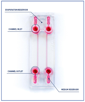
Beonchip device: Be-Flow
The design of the Be-Flow consists of 2 independent channels with threaded inlets and outlets enabling the insertion of connectors and tubing coupled to fluidic controllers. It is possible to apply an independent flow rate in both channels using any perfusion system. To avoid culture media evaporation during the onset of the experiment (before perfusion has started), water-filled reservoirs are positioned next to the medium reservoir (scheme).

FLUIGENT equipment
Fluigent positive pressure controllers precisely regulate the flow rate of a microfluidic system by applying small air pressures (mbar) over a closed reservoir to induce the rise of a solution through an output tube.
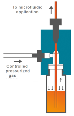
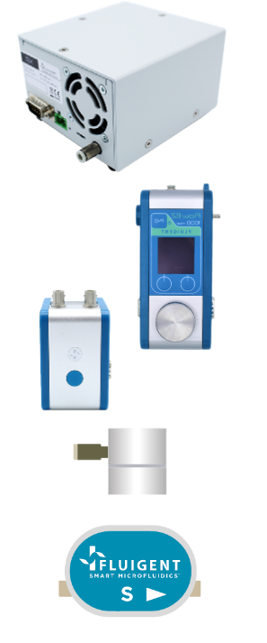
- Air pressure source. This can be a compressed air intake or external compressor. The use of the external pressure compressor (FLPG or RX) will facilitate the assembly of the system under a biosafety cabinet to perform cell culture experiments under sterile conditions. Once the system is assembled and placed inside the incubator, it can be connected to a fixed compressed air intake.
- Flow-EZ pressure controller. The pressure controller is capable of regulating the air inlet to the liquid reservoir to displace it.
- Link / Power supply module. The link module (linked to the FlowEZ pressure controller) allows the connection to a PC for software control.
- CAPs. Caps for the hermetic closure of reservoirs.
- FlowUnit. Linking a flow sensor to the pressure controller allows direct control over flow rate. The flow sensor will always be placed after the outlet reservoir and before the microfluidic device.
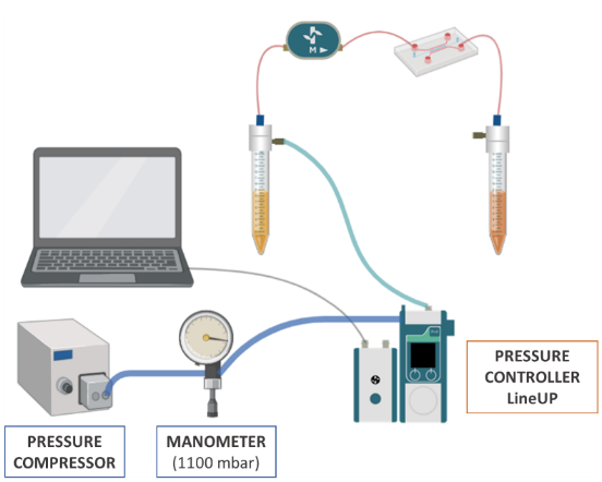
The fluidic system configuration is represented in the illustration:
• Pressure compressor RX
• Regulator
• FlowEZ (1000 mbar)
• FlowUnit S
During assembly, connect the Flow Unit in the direction of flow, indicated by the arrow on the Flow Unit. Before starting the experiment, calibrate the pressure to ‘0’ on the pressure controller. To do this, manually set a pressure of ‘0’ and click on the option “pressure calibrate” from the menu in the controllers.
Use the P=0 button
Methods
Be-Flow cell culture
Before cell seeding, pre-warm the Be-Flow standard device in the incubator overnight to minimize the formation of air bubbles.
- Fill the channel with 100μl of collagen at 0.1 mg/ml (in PBS 1X) and incubate at 37°C for 30 minutes. Wash the channel by adding 100 μl of PBS 1X into the inlet and by aspirating it at the outlet using P200 pipette. Repeat this step three times.
- Aspirate PBS 1X completely before cell seeding.
- Seed 1.106 Caco-2 cells resuspended in 50μl of culture media.
- Incubate at 37°C, 5% CO2 until the cells have properly spread (2-4h).
- Once cell spreading has occurred, add 300μl of culture medium into the medium reservoirs. Add H2O to the evaporation reservoirs, cover and keep it in the incubator until the perfusion set up is ready to be connected (around 2h).
For more information, see:
- Be-Flow coating and culture (video).
- BF standard (pdf)
- Connecting a microfluidic control system (video).
- Rocker (video).
If connection to a perfusion system is not possible for more than 2 hours following cell seeding/cell spreading, keep the device in the incubator and renew culture medium using a rocker as long as needed. Check the channel has enough fluid and does not dry up.
Microfluidic set up
Before setting the flow up:
- Sterilize and pre-warm the tubing and the fluidic elements overnight at 37°C.
- Put the system under a laminar flow cabinet.
- The channels and inlets/outlets should never be depleted of culture medium.
- Both inlets and outlets use connectors (1/4’’ – 28).
To work with cells, the assembly of the circuit must be carried out under sterile conditions under a biosafety cabinet. Before use, autoclave the CAPs, pneumatic tubes, threaded connections and ferrules to be used.
- Connect all circuit components except the microfluidic device.
- Establish a flow of ethanol (70%) for at least 15 min to sterilize the sensor and then wash with abundant sterile H2O. Dry by passing air through at maximum pressure. The sensor CANNOT be autoclaved.
- Prime the tubes of the circuit with culture medium until there are no air bubbles.
- Remove the culture medium from the chip reservoirs (not from inlet/outlet wells) and connect the tubes to the outlet/inlet using the threaded connections and ferrules.
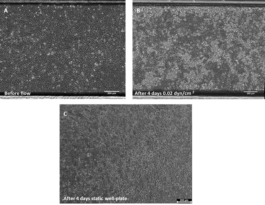
The ferrules should be manipulated with the help of sterile forceps. Ensure that the tube is perfectly fixed. Remove any displaced medium from the reservoirs. - Once the system is closed, set the flow to 5.8 μl/min (shear stress 0.02 dyn/cm2) for 4 days to promote villi formation. Observe the system under perfusion for a few minutes to check that there are no leaks.
For more information check the following tutorials:
Microfluidic set-up
1. Flow EZ: Getting started
2. Flow EZ: Insert in my setup
3. Flow EZ: Add my FLOW UNIT
Results
After 4 days of perfusion, flow is stopped and the system is placed under an inverted microscope to monitor cell behaviour/differentiation. As observed in Figure 1, cell density is increased after 4 days of culture under flow conditions. Furthermore, Caco-2 started to form 3D structures, features not seen under static conditions.
Authors
This article has been written by Sandra González Lana.
Bibliography
1 N. Ashammakhi, R. Nasiri, N. R. de Barros, P. Tebon, J. Thakor, M. Goudie, A. Shamloo, M. G. Martin and A. Khademhosseni, Biomaterials, 2020. DOI:10.1016/j.biomaterials.2020.120196.
2. H. J. Kim, D. Huh, G. Hamilton and D. E. Ingber, Lab Chip, 2012. DOI: 10.1039/c2lc40074j
3. A. Grassart, V. Malardé, S. Gobaa, A. Sartori-Rupp, J. Kerns, K. Karalis, B. Marteyn, P. San –
sonettti, N. Sauvonnet. Cell Cell Host Microbe. 2019. DOI: 10.1016/j.chom.2019.08.007
4. HJ. Kim, DE. Ingber, Integr Biol (Camb), 2013. DOI: 10.1039/c3ib40126j5.

