

Summary
At Beonchip, we provide standard cell culture platforms and the option to customize the channel dimensions or membrane pore size. Additionally, we offer services to adapt the device design for specific research needs. In this note, we’ll summarize the results of a recent collaboration between Beonchip and the University of Zaragoza. This study explored improving contact area with custom microfluidic devices inspired by the Be-Transflow system, testing various designs to reduce inert materials while maintaining effective cellular distribution.
Read the full article here.
Introduction
Microphysiological systems such as our microfluidic devices are characterized by small compartments, usually channels and wells, that allow the confinement of different cell types in the same model [1]. The intent to replicate the organization of native tissues is accomplished with the use of inert materials on these chips, such as membranes [2]. However, these structures differ in aspects (composition, mechanical properties) from the physiological environment [3].
For some applications, the physical separation of these platforms can limit cell-cell interaction and migration. The cell-matrix interactions in the breast tumour microenvironment or axon’s guidance on the brain are two examples of phenomena that would value a model with less inert materials separating the cells and biomaterials [4,5].
Considering this information, the primary aim of this research was to reduce the amount of physical barriers in the microfluidic device, while ensuring the proper distribution of cells. Researchers created two microfluidic devices to accomplish this aim by altering the membranes that separate the compartments in the designs.
Be-Transflow-inspired devices developed
In the initial design, referred to as the Mesh device, a nylon mesh with regularly spaced pores of 150 µm was integrated into our Be-Transflow device. This membrane was used to reduce the inert material by 55% of the total area, facilitating direct cell contact. Furthermore, the manufacturing process for this approach enabled the inclusion of meshes with varying pore sizes to achieve larger contact areas when necessary. Conversely, the second design incorporated an inert COC-Flex membrane housing three macropores, each measuring 1 mm diameter. This approach termed the Macropore device, was employed to promote direct cell-scaffold interaction, with the contact area reaching 100%, effectively eliminating inert materials from the contact zone. To validate these devices, permeability and diffusion assays were conducted, comparing their performance with chips featuring conventional polycarbonate (PC) membranes with around 5% porosity.
Finally, three potential biological applications are outlined in the designs. The first involves generating a human epithelial layer using the Mesh device. The second showcases migration models of glioblastoma multiforme (GBM) within a collagen hydrogel layer, using both the Mesh and Macropore devices. Lastly, the third model demonstrates the generation of another epithelial monolayer, along with its connective tissue and native stromal cells, employing the Macropore device. The findings demonstrate that removing inert materials from the chips can improve direct cell and matrix contact without compromising the compartmentalization of the designs.
Mesh Device
Design
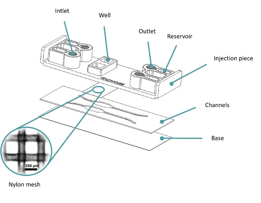
Figure 1: Design of the Mesh device. Image collected from original paper [6].
The Mesh device was based on Beonchip’s standard Be-Transflow device, composed of two parallel channels connected to two open wells through a porous membrane. In the Mesh device, a 150 µm pore size nylon membrane was used, instead of the standard 1 µm pore size PET membrane(Figure 1).
This design allowed the decrease of inert material by 55% on the membrane, endorsing the direct contact between cells seeded on the well and channel.
Epithelial Layer
To validate the culture on top of the new membrane, researchers placed human colon cancer spheroids onto the membrane, allowing them to cover the entire mesh and progressively form a cellular monolayer over the 12 days of culture (Figure 2A). Initially, within the first 24 hours, cells began to gradually extend from the main mass and started encircling the nylon mesh. Subsequently, in the following hours, the cells filled the vacant spaces between the nylon threads, forming a cohesive cell layer. Finally, by the end of the experiment, cells had expanded over 95% of the total well area, successfully creating a viable monolayer of cells (Figure 2B).
Therefore, this result validated the ability to create cell monolayers within a membrane featuring larger pores.
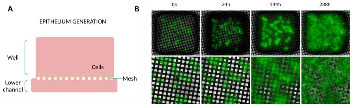
Figure 2: Epithelial layer formation on Mesh device. (A) Diagram illustrating the culture setup. (B) Evolution of the monolayer on top of the membrane at different time points (0, 24, 144, and 288h) (top view). Bottom layer images are magnifications of the top layer images. Scale bar top images: 1 mm. Scale bar bottom images: 100 µm. Images collected from original paper [6].
Migration Model
Researchers used human glioblastoma cells in a migration assay to validate the device. Initially, they seeded the cells in a spheroid configuration, embedding them in collagen and placing them above a collagen layer on the well (Figure 3A). To encourage migration toward the mesh, they subsequently created a nutrient gradient by adding low-glucose media to the top of the hydrogel and high-glucose media supplemented with non-essential amino acids to the bottom channel.
As a result, the cells migrated from the top hydrogel layer, where they were embedded, to the layer below within the first day. By the end of 96 hours, the cells had successfully moved through the mesh and into the bottom channel, where the nutrient gradient was strongest (Figure 3B).
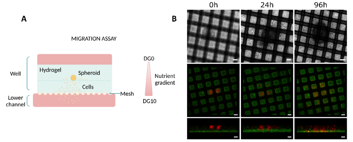
Figure 3: Migration studies on Mesh device. (A) Diagram illustrating the culture setup. (B) Evolution of the migration of U-87 MG cells at different time points (0, 24, and 96h). The top row corresponds to top view bright-field images. The Middle (top view) and bottom (side view) rows correspond to confocal images. Scale bar 100 µm. Images collected from original paper [6].
Co-culture in the Mesh Device
Researchers cultured glioblastoma cells in the well of the Mesh device using the same method. Additionally, they seeded endothelial cells in the bottom channel (Figure 4A). After 24 hours, the glioblastoma cells successfully migrated onto the mesh and established contact with the endothelial cells (Figure 4B).
Therefore, these results confirm that the mesh’s increased contact area effectively facilitates direct contact between the two cell types.
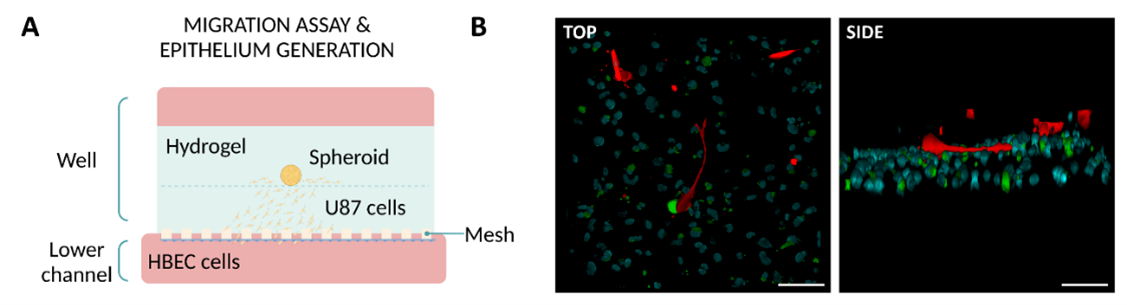
Figure 4: Co-culture in the Mesh device. (A) Diagram illustrating the culture setup. (B) Z-stack reconstruction of confocal images showing the interaction between glioblastoma cells (red) and endothelial cells (green with nuclei stained blue). Scale bar: 100 µm. Images collected from original paper [6].
Macropore Device
Design
The Macropore device introduces a design that significantly deviates from the standard Be-Transflow device. This device features two parallel channels connected to two wells, but in this case, the connection is made through two cyclic olefin copolymer layers. Specifically, one layer includes two Ø4 mm wells, while the other contains six Ø1 mm wells. By overlapping these layers, each channel aligns with one Ø4 mm well and accommodates three macropores (Ø1 mm) (Figure 5).
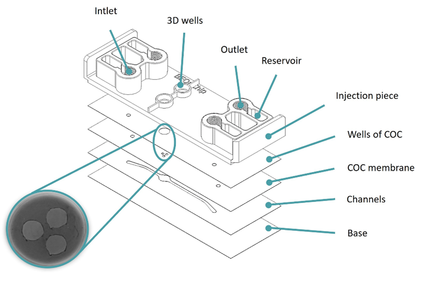
Figure 5: Design of the Macropore device. Image collected from original paper [6.]
This design increased the contact area between cells to 100% for a mesh that no longer separated the channel from the well.
Migration Model
Similar to the migration assay performed on the Mesh device, researchers seeded glioblastoma cells into a collagen hydrogel within the well and introduced a nutrient gradient by adding low-nutrient media on top of the hydrogel and high-nutrient media to the bottom channel (Figure 6A). The cells began migrating as early as the next day, and after three days, they successfully reached the bottom channel (Figure 6B).
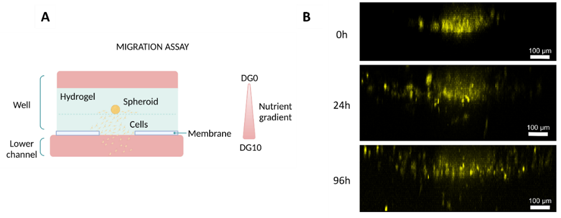
Figure 6: Migration studies on Macropore device. (A) Diagram illustrating the culture setup. (B) Lateral view of 3D projections of confocal images at different time points (0, 24, and 96h). Cells were artificially coloured in yellow to highlight their movement towards the channel. Scale bar: 100 µm. Images collected from original paper [6].
Co-Culture in the Macropore Device
Furthermore, researchers used the Macropore device to co-culture intestinal epithelial cells with dermal fibroblasts. First, they embedded fibroblasts in a collagen hydrogel and seeded them into the well. Next, they seeded intestinal epithelial cells on top of the hydrogel and added media to the top layer (Figure 7A).
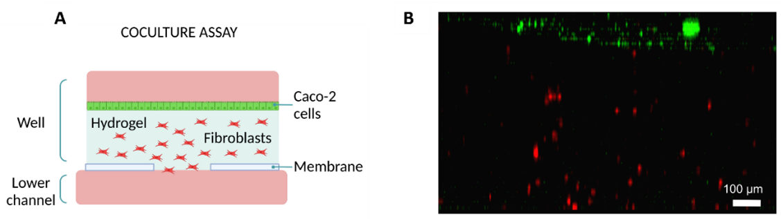
Figure 7: Co-culture on Macropore Device. (Diagram illustrating the culture setup. (A) Diagram illustrating the culture setup. (B) Lateral view of 3D projection of a confocal image after 24h. Intestine epithelial cells are shown in green and fibroblasts in red. Scale bar: 100 µm. Images collected from original paper [6].
After 24h, fibroblasts were distributed throughout the hydrogel and endothelial cells formed a monolayer on top of the hydrogel (Figure 7B).
Permeability Assessment
To evaluate permeability, the team compared the Mesh device, the Macropore device, and a device with a PC membrane as a control. They introduced fluorescein into the well on top of a collagen hydrogel or a hydrogel embedded with human colon carcinoma cells. Subsequently, they collected media from the bottom channel and quantified the concentration of fluorescein. Finally, they compared the results across all three devices.
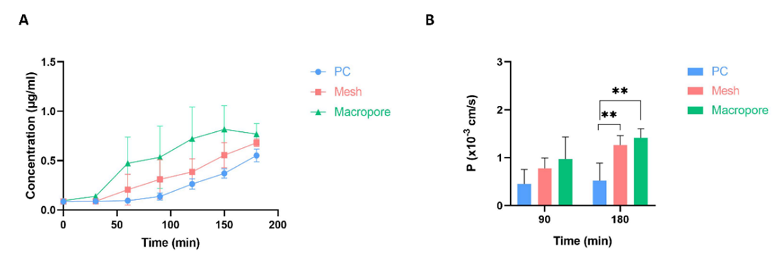
Figure 8: Permeability assays. (A) Evolution of fluorescein’s concentration diffused through a collagen hydrogel in three devices: Mesh, Macropore and one with PC membrane as control. (B) Permeability coefficient values for the three devices at two different time points (90 and 180 minutes). Data are represented as the mean ± SEM (**P < 0.01; n=3). Images collected from original paper [6].
On the devices without cells, the Macropore device had the highest concentration of fluorescein collected in most time points, followed by the Mesh device and lastly, the PC membrane device. This trend was observed throughout the time points (Figure 8A).
As for the experiments with cells embedded in the collagen hydrogel; Macropore device also presented the highest concentration of fluorescein in the bottom channel, followed by the Mesh device and finally the PC membrane device. By the second time point (180 min), there was a significant difference between the Macropore and Mesh devices when compared with the PC membrane one (Figure 8B).
Conclusions
The goal of creating more biomimetic experimental models focuses on minimizing the use of inert materials in microfluidic devices. To achieve this, researchers designed two innovative devices aimed at improving the contact area with custom microfluidic devices. These devices incorporate membranes with sufficiently large pores to promote significant interaction between cells and extracellular matrices.
The first device, called Mesh, integrates a nylon membrane with evenly spaced pores measuring 150 µm in diameter. In contrast, the second device, named Macropore, features a flexible COC membrane with larger macropores, 1 mm in diameter. Furthermore, both devices have undergone biological validation through assays that assess cell migration, epithelium formation, and 3D co-cultures, demonstrating their effectiveness in advancing biomimetic modeling.
Read the full article here.
More information about the Be-Transflow Custom devices can be found here.
Bibliography
1. Monteduro, A. G. et al. Organs-on-chips technologies–A guide from disease models to opportunities for drug development. Biosens. Bioelectron. 231, 115271 (2023).
2. Pasman, T., Grijpma, D., Stamatialis, D. & Poot, A. Flat and microstructured polymeric membranes in organs-on-chips. J. R. Soc. Interface 15, 20180351 (2018).
3. Moeendarbary, E. & Harris, A. R. Cell mechanics: principles, practices, and prospects. Wiley Interdiscip. Rev. Syst. Biol. Med. 6, 371–388 (2014).
4. Jones, M. J. & Jones, M. C. Cell cycle control by cell-matrix interactions. Curr. Opin. Cell Biol. 86, 102288 (2024).
5. Ana, V.-A. & Elisa, T. Cell-Cell and Cell-Matrix Interactions during Axons Guidance. in (eds. Abreu, G. E. A. & Aguilar, M. E. H.) Ch. 1 (IntechOpen, 2018). doi:10.5772/intechopen.79681.
6. Olaizola-Rodrigo, C. et al. Reducing Inert Materials for Optimal Cell–Cell and Cell–Matrix Interactions within Microphysiological Systems. Biomimetics vol. 9 at https://doi.org/10.3390/biomimetics9050262 (2024).